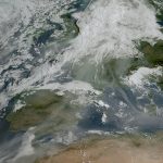
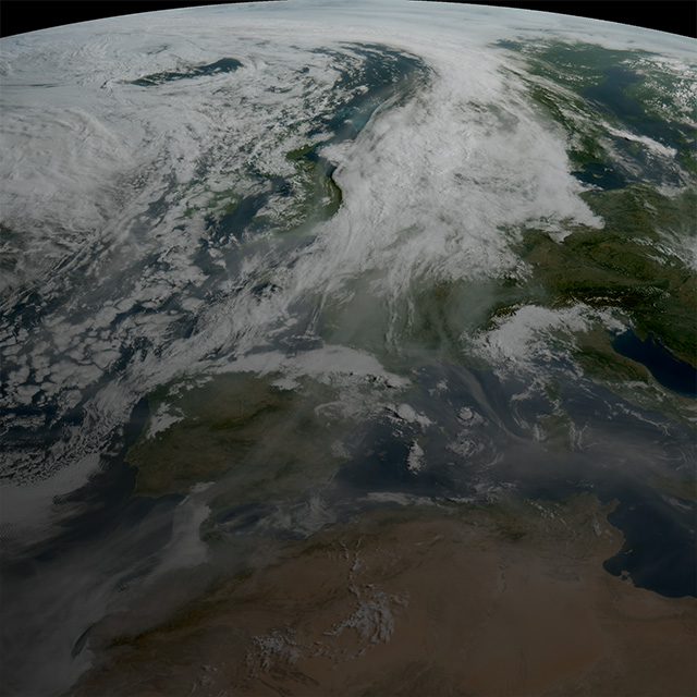
The Same Face of Machine Vision

So, I was fortunate enough to attend the AIA Vision Show last week. I had some meetings lined up, toured the show, spent time on our booth, checked out the other booths, joined a presentation that was going well until it faded to black… stalked a few competitor booths to review their marketing content, and met with a few familiar faces at the show — which brings me to my point.

So I've been with DALSA (Teledyne DALSA) for a number of years, and in those years, I'd say it feels like only a handful of faces have changed. Not just here, but more generally when I see people from time to time at shows.

We've grown mostly through acquisition so some of the familiar faces are now colleagues; other companies have consolidated and morphed into new ones, and it seems to me, on the whole, the faces change infrequently. It seems that few people leave the machine vision industry. Am I wrong? I've noticed there are familiar faces in the crowd who appear, and re-appear from show to show and that overall, the show itself feels a bit like a homecoming weekend — without the football game, and with less beer. I'm not saying this is a bad thing.

Which got me to thinking… so what is it that keeps people here? Is it for the love of the technology? Is it a passion for increasing bandwidths and higher resolutions? or maybe a deep yearning for an ever-faster connection speed? Is it that with every new idea for automation, the very thought of a new level of vision inspection is a lure that keeps people coming back? Maybe it's about pushing the very limits of whichever piece of vision you're involved in that does it.

Or maybe it's as a colleague suggests, you choose a course of study and a path. You live and breathe it and grow with the technology until… surprise, you're at 20 years, and you can't imagine yourself doing anything else — which speaks to me of both commitment and dedication. Two qualities you'd want from an expert in a category that so heavily shapes the quality and production of materials that drive economic growth and play such a critical role in our future.

'til next time.

Posted on by Geralyn in Machine Vision | Leave a comment

Image Filtering in FPGAs

Anthony

Image filters — like Gaussian blurring, median filtering, and morphological operations, are indispensable tools in image pre-processing. But with the increasing bandwidth requirements today, such pre-processing tasks can be offloaded to a parallel processing hardware monster known as an FPGA (Field Programmable Gate Array).

FPGAs are reconfigurable devices that contain small Look-Up Tables (LUTs), small memories (Registers), larger block RAM (BRAM), and dedicated multipliers. The user basically programs the connections and parameters for these blocks. FPGAs excel in high parallel processing tasks and, although they typically operate at lower frequencies than CPUs, for a given task they can easily outperform a CPU by orders of magnitude.

From a purely software perspective, images are 2D arrays that reside in memory. A 3×3 convolution in software pseudo-code would look as shown below. This will roughly take 9 multiplications and 8 additions; these will be executed in a serial fashion (more or less).

for (y = 1; y < ImageHeight-1; y++){
    for (x = 1; x < ImageWidth-1; x++){
        O[x][y] = c0*I[x-1][y-1] + c1*I[x][y-1] + c2*I[x+1][y-1] +
                  c3*I[x-1][ y ] + c4*I[x][ y ] + c5*I[x+1][ y ] +
                  c6*I[x-1][y+1] + c7*I[x][y+1] + c8*I[x+1] [y+1];
    }
}

But from an FPGA paradigm images are simply pixel streams coming in as a raster scan one at a time (or a packet of them at a time) from top-left to bottom-right, and since FPGAs are rather limited in terms of internal memory, they typically store lines rather than frames (unless when necessary, in such cases external memory would be used).

A 3×3 convolution in an FPGA would look as follows:

The line buffers act as a latency pipe and delay the incoming streams by a factor of the line width (wider images will require more resources). This will have the effect of sliding a 3×3 window in raster scan over the image. The 3×3 kernel stream is then passed to the filter core which performs the actual calculations.

For the actual filtering core a Finite Impulse Response (FIR) filter is implemented, 9 multiplier blocks can be used in parallel with an adder chain (or an adder tree); hence we are able to treat 1 pixel every clock cycle as shown below (register pipelining is not shown):

That same architecture can be extended to support more taps or pixels in parallel (e.g. 8 or 16) making it a powerful, high-throughput, pixel crunching machine!

Food for thought:

  • Dedicated multipliers can operate at higher frequencies than the remaining FPGA fabric; hence you can use less multipliers and accumulators at a faster rate.
  • If your filter is symmetric you can use a pre-adder to save the precious multipliers.
  • If your [3x3] 2D filter kernel is separable then you might save resources by performing a [3x1] followed by a [1x3] convolution.

FPGA image processing can be performed inside smart frame grabbers and cameras. Compared to software implementations, this offers users both the freedom and flexibility to tailor a processing stage to their bandwidth requirements. Keep in mind though that in most cases, this may amount to a trade off between speed and resources.

Posted on by Anthony in Frame grabbers, Image processing | Tagged , | Leave a comment

The Angle on Optical Acceptance

Matthias

In my last post — not the April Fools post — but the one before… I described how pixel Fill Factor plays a role in the optical efficiency of an image sensor.

The Optical Acceptance Angle is directly related to Fill Factor but not very often discussed or specified. Misjudging this effect can impact image flatness and color quality in optical systems.

Consider the following optical system:

A lens is sketched, focussing on a simplified pixel array (micro lenses only). The tracing lines illustrate the center pixel (green) with decent incidence angles as well as the outermost pixel (red) with extreme (exaggerated) angles.

This wide distribution of incoming angles is essentially the issue a larger image sensor faces in an optical system.

If we look at the pixel in more detail and simplify the incoming angle distribution to the extremes we get the following pictures.

With increasing incidence angle more light rays fall onto metallization or neighbouring pixels. As a result the pixel output signal will decrease with increasing incidence angle. Signal is "shared" between neighbouring pixels, degrading MTF and creating optical (colour) crosstalk.

To improve or resolve these non-idealities, pixel designers employ ray-tracing simulations.

The illustration below is an actual sensor with a high-end lens at infinity focus and f1.6 aperture. The light rays are shown as parallel bundles arriving with the extreme angles the lens will produce (upper and lower Coma rays). The resulting "focal cones" need to be considered when designing the pixel.

Center Pixel, system lens at f1.6. Optimized micro lens position. Center & Coma rays shown

Center Pixel, system lens at f1.2 — Optimized micro lens position. — Center & Coma rays shown. Pixel Acceptance Exceeded

The "effective aperture" of a pixel (for a given lens) is reached when further widening of the lens aperture (or: wider spread on Coma rays) results in lesser rates of signal increase on the sensor output. Each f-stop should double the output signal.

Designers can optimize a pixel, such that it is maximally responsive to this incoming focal cone for a lens with known Coma ray behaviour. Pixel size, metallization density and stack height do set physical limits, however.

Adding the physical extension of the image sensor (remember the “red” rays in the first figure) the above Coma ray range has an “offset” in the form of a non-zero Chief-Ray-Angle (“CRA”). For simplicity we can think of the CRA as the center ray of the focal cone.

The lens in this design shows narrowing Coma extremes off-normal but the default pixel still shows aperture reduction (left image). A typical way around this new problem is called "shifting" (shown on the right). Shifting is done for both colour filters and micro lenses and is measured as a function against the pixel optical axis. We show the edge pixels illuminated as above, but with a lens shift of ~1/10 pixel pitch. (Note that the optimized lens position for the center pixel was already shifted).

Edge Pixel, system lens at f1.6. Center-Pixel micro lens position. Coma rays at non-zero Chief Ray Angle.

Edge Pixel, system lens at f1.6. Optimized micro lens position. Coma rays at non-zero Chief Ray Angle

While these results are quite good (accepted aperture ~f1.2), the analysis was done for one lens series! One can do a bit better and show that lens families (e.g. high-end Digital Cinema lenses from one manufacturer) can be reasonably well serviced with this method. Using a different manufacturer or a different lens family can completely upset this design and result in colour distortions and lack of flatness again.

And this is why lens shifting is not usually the practice in a variety-rich environment like Machine Vision. A system can be optimized for a certain application, but not for all of them at once.

Gotta love variety,

Matthias

Posted on by Matthias in Image Sensors, Machine Vision | Tagged , | Leave a comment

My Favourite “Easy®” Button

Paul

Thomas Edison once said, “Genius is one percent inspiration and ninety-nine percent perspiration.” I have to admit that I don’t like that ratio very much. Perhaps I don’t aspire to be a genius. I would much prefer to spend more of my time on project work thinking and planning rather than doing. Unfortunately, by its nature, IC design includes many repetitive tasks – tasks so mind-numbingly boring that I can’t help but turn my brain off and switch into auto-pilot. These mundane tasks are so completely hypnotic that by the end of the day, I realize I’ve only blinked twice, my neck is sore from keeping my head 15 cm away from the monitor, and my shoulder aches from excessive mouse usage. On occasion, I arrive at work the next day to find that while my brain was on auto-pilot the day before, I did something I should not have, and I can look forward to spending at least part of my day in re-work. Yes, I am pretty sure I’d rather spend more of my time thinking than doing…

…which brings me to the topic of design automation. Automation, when used with care, can make life easier even with the most precise design requirements. We have a team of CAD tool experts who understand this very well. My favourite utility they've created so far is one that automatically creates wires and labels in a schematic simply by clicking on an instance. While it won't draw the whole schematic for you, the time you save by not having to type in the net names is incredible! We also have a navigation tool that eliminates the need to constantly change the zoom level in the layout. Another tool creates what we call “special pins”, which are really not so special at all, but special enough that standard EDA tools couldn’t do the job we wanted. This tool allows us to drop an array of odd or even numbered pins at a user-defined spacing.

I find that my design team is much more tolerant of manual processes than I will ever be. I am trying to find ways to motivate them to look for ways to improve efficiencies through automation. I recently purchased an “Easy®” button from Staples. If you're not familiar with it — every time you push it, it says "That was easy!" Any time one of the designers either suggests or implements a new idea for automation, they get to push the button at our group meeting. I am sure this tactic will soon lose its lustre, but my hope is that the seed is planted in their minds to look for efficiency rather than sticking with brute force design methods. My next step will be to get the team thinking more about how automation can be used during the evaluation phase of projects.

What do you think? Do you have a favourite “Easy®” button?

Posted on by Paul in Machine Vision | Leave a comment

Looking at transfer bandwidth from another perspective

One thing I've learned from my years in Machine Vision is that performance and bandwidth are never enough to satisfy leading edge applications; hence the constant quest to increase the transmission speed of camera interfaces. Teledyne DALSA has always been at the forefront of this chase and the GigE Vision standard is no different: GigE Vision 2.0's primary mandate was to find ways to increase the bandwidth between camera and PC.

For obvious reasons, people looking to increase bandwidth take a straightforward approach to the problem: simply increase clock speed on the cable! For GigE Vision, this leads to the usage of 10 gigabit Ethernet. This is certainly a valid approach — although an expensive one, may I say. But one can look at this problem from another perspective: if the goal is to transfer more images in a shorter period of time, why not consider image compression?

You are going to say image compression leads to loss of information. And you are right. Compression means throwing away “less important” information, typically the high frequency content. But a study from Ebrahimi, Chamik and Winkler (see reference below) teaches us that the most advanced image quality authority, the human eye, does not see any visible degradation when using JPEG with a compression ratio less than 5. And if your eyes cannot see compression artifacts when they can definitively see sensor-induced noise, wouldn't you consider image compression a valid option to reduce bandwidth? Additionally, most image compression algorithms, to a greater or lesser degree, filter out high frequency content, and noise typically fits in this category.

GigE Vision 2.0 (a free download from the AIA web site) is the first Machine Vision camera standard to natively enable usage of image compression. It introduces support for JPEG, JPEG 2000 and H.264. I admit data compression is not suitable for all applications, but this is an interesting low cost way to look at increasing the frame rate between the camera and the PC, with the added benefit that data archiving frequently relies on compression. So the next time you need to increase transmission bandwidth, you might open your wallet or you might take a look at alternative strategies, such as image compression.

Cheers!

Reference: JPEG vs JPEG2000: An Objective Comparison of Image Encoding Quality, Farzad Ebrahimi, Matthieu Chamik, Stefan Winkler, http://stefan.winkler.net/Publications/adip2004.pdf

Posted on by Eric in Cameras, Frame grabbers, Interface Standards, Machine Vision | 1 Comment

Imaging as Life Changing Technology

Brian

Recently, I was asked to speak at our Manufacturing team's "town hall" to describe what our Life Science and X-Ray group are up to. Generally, I believe that individuals are more engaged in their work when they have an understanding of its real value. The real value of the product I am involved with can best be described as immediate and far-reaching in its ability to improve lives.

Looking at the audience, I could see that roughly 50% were women, and potentially impacted directly by my topic. The men in the audience have mothers, daughters, wives or girlfriends, so I knew what I was about to speak about would have impact for them too. My topic? Breast cancer.

First, some unfortunate statistics.

  • 1 in 9 women develop breast cancer
  • 1 in 29 die as a result.
  • It is the #1 form of cancer detected in women.

From 1986 to the present, the death rate from breast cancer has dropped by more than 25% and now, 88% of women diagnosed are surviving past the 5 year mark. It can be argued that this improvement is a result of improved screening and detection. Detection at the earliest point in its development plays a critical role in improving chances of survival.

In recent years I have had the honour of leading the development of an X-Ray TDI detector used for mammography. Turns out our Charge Coupled Device (CCDs) technology is well suited to mammography applications. Perfectly sized pixels (just small enough to achieve top performance without being unnecessarily small) help with improved resolution, hence the ability to see smaller microcalcifications in the breast. We developed a die-butting and assembly capability that allows for the field of view necessary to scan the human breast. Anti-blooming allows for an improved view of the skin line around the periphery of the image — a key feature that radiologists look for. And because the risk of x-ray exposure during a scan is such a hot topic, the ability to resolve features at a lower dose is a distinct advantage of the TDI modality. Finally, it cannot be overlooked that a faster scan means an uncomfortable procedure is over more quickly. I truly believe that the developments we are involved in now, and those we're working on for the future will help us move the mortality rate down a further few notches.

It seems breast cancer has always been near me; my grandmother survived it, and my wife had a breast cancer scare at a relatively young age. I was lucky to be given the opportunity to work in the field of mammography and have this kind of an impact — one that can be so easily linked to saving lives. But I generally see technology as an enabler for improving lives, no matter the form that takes. When you get your chance to improve quality of life through technology, my advice is to make the most of that chance. It's bound to be both rewarding and motivating at the same time — and something I believe we're all called to.

Posted on by Brian in CCD, Medical Imaging, Time Delay & Integration | Tagged , , , , , | Leave a comment

Excellent post on better lighting for line scan applications

Hi,

Just a quick note to share with you a recent post by B Grey. Check it out here.

Posted on by Geralyn in Machine Vision | Leave a comment

Sowing the Seeds of Camera Link HS

Mike

Its spring time finally, a time of new beginnings and a time to get out in the garden and start planting in anticipation of the harvest to come. In my mind, technology and product development are a bit like gardening – you prepare the soil, plant the seeds, water and care for the plants and then you get to watch things grow.

The Camera Link HS (CLHS) committee has been carefully preparing the soil to achieve the balance of nutrients/features needed for machine vision today and for many years to come. The CLHS soil is rich and planted, ready for growth and harvest.

A good gardener plans his garden. This can be both difficult and exciting when trying something new. Careful evaluation of CLHS technology reveals that new crops of cameras and frame grabbers can benefit from the advantages of:

  1. Multiple vendor support for device and system components.
  2. Direct drive from FPGAs that enable low cost, small size, low power and long supply life.
  3. Proven base technology leveraged from high volume industries and successfully deployed now by Teledyne DALSA for the last 2 years in HS Link products.
  4. A single copper cable with a 15 metre distance and 2.1 Gbytes/ sec bandwidth, suitable for most applications.
  5. Fibre optic cabling to achieve greater than 300 metre distance, low cost, small size, light weight, high flex life, immunity to ground bounce and electrical fields and noise when flexed, and up to 10 Gbps lane speeds.
  6. Packed data formats that deliver optimal transfer efficiency while frame grabbers ensure minimal CPU loading and may include image pre-processing functions.
  7. Error detection and data re-transmission methods to ensure vision systems meet customer expectations.
  8. Plug and Play technology onboard, GenICam and standardized LED definitions.
  9. Parallel processing by identical frame grabbers with multi-cabled cameras achieve higher bandwidths and lower system costs.

The committee is seeding the landscape with reference designs to help ease development times and ensure device interoperability. Reference designs can be licensed from the AIA in May. In addition, the standard allows each gardener to differentiate their product and offer something unique to their customers.

CLHS is a G3 (Cooperation Agreement on Global Coordination of Machine Vision Standardization) approved standard. The specification was released for public review on March 1st and can be obtained from the AIA, European Machine Vision Association (EMVA) and Japan Industrial Imaging Association (JIIA). The committee continues to work on the product qualification process, enhance the adoption collateral, and of course enhance the feature set of the standard.

Happy Planting!

Posted on by Mike in Cameras, Frame grabbers, Image processing, Interface Standards, Machine Vision | Leave a comment

CMOS Group Advances Flexible Imaging Technology

Matthias

I think I'm finally getting the hang of this blogging thing — and while we have a requirement not to prattle on about IP, I'm pretty sure what I'm about to share with you will be announced shortly anyways.

We’re in the design phase of a revolutionary, next generation image sensor to address a multitude of markets and benefit machine vision system designers from the factory floor to large scale OEMs. Expectations are that this latest chip will fully eclipse today’s technology for general machine vision — especially for food and environmental inspection. The chip will be available in 3 resolutions, 1, 4 and 12 Megapixels with two primary pixel sizes – 5 and 25 µm. Starting with the base pixel, the sensor field-of-view can be adjusted to meet most requirements, covering a range of 5 –100µm pixel pitch. Continue reading

Posted on by Matthias in Machine Vision | 3 Comments

Turnkey solutions — the challenge of integration

Daniel

As imaging experts, we are asked to provide imaging solutions to our customers. Most of the time, we provide part of the solution: a frame grabber, a camera, some software libraries, in other words, generic imaging components. Sometimes customers are more specific: they want a turnkey solution ready to be deployed. And this is where the fun starts.

Customer requests like these normally turn into development projects. From project management books, we know that a high percentage of projects fail, and for a variety of reasons, including but not limited to:

  • requirements that are not well defined
  • incorrect evaluation of the scope of work
  • bad resource management (which results in missed deadlines and product functionalities that do not meet customer expectations)

Imaging projects are no different. Continue reading

Posted on by Daniel in Image processing, Machine Vision, Software | Tagged , , , | Leave a comment